

The heating elements, PCBA, and temperature control circuits used in the wearable heating system have to be a whole system- the effectiveness of performance, safety, and lifespan can be determined by the quality of integration as opposed to the specifications of particular components.
Even heating elements are passively oriented devices. They can be Joule heated in which current passes through a resistive substance such as carbon fiber, heating wire or printed conductive film. The element produces heat in direct proportion to the square of the current and its resistance (P = I 2R), and it lacks any internal sense of its own temperature, or of a faulty condition.
The actual control and safety intelligence is in the surrounding electronics, especially the Printed Circuit Board Assembly (PCBA) and the temperature control circuits embedded within it. Another myth that most designers believe in is the fact that the requirement to use a high quality heating element leads to safe and stable operation. As a matter of fact, the finest component, when it is not properly integrated, may cause thermal run-away, non-uniform heating, early breakdown, or hazards to the user.
The paper is based on real-world experience of the development of embedded systems to control heated clothing, which points out the interactions between these components on electrical, thermal, and mechanical levels.
The Role of PCBA in Wearable Heating Systems
The PCBA is the brain of any battery operated heated clothing. It manages various vital processes that normally interface with the heating component.
MOSFETs or other power transistors usually control power switching by switching the heating current on and off at a rate to generate variable heat output without consuming energy to linear control it.
Present regulation guarantees that the heating element is fed a steady power despite changes in the voltage of the battery or fluctuations in the resistance of the element with temperature. Constant-current driver designs or feedback loop designs will be used in many designs to stabilize the output.
Safety monitoring involves voltage supervision, current limiting, fault detection circuit which avoids occurrence of overcurrent condition to damage the system.
Understanding the electronic architecture of wearable heating systems provides essential context for how the PCBA fits into the broader electrical composition and structure.
Key PCBA Components for Heating Control
- Logic processing microcontroller or dedicated ASIC.
- High current switching Power MOSFETs.
- Monitoring current-sense resistors.
- Undervoltage or overvoltage protection ICs.
Power Delivery from Battery to Heating Element
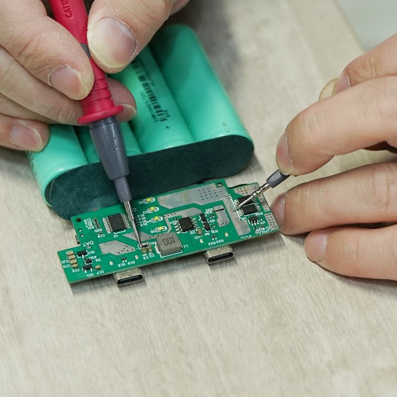
The rechargeable lithium-ion battery (usually 7.4 V or more) begins power delivery to the PCBA. This voltage is stepped by the board when it is required, typically, as a direct feed to the heating component to minimize the expense, and controls current paths through low-resistance traces and connectors.
The heating element needs to have the same profile of resistance to voltage input as otherwise it will either draw too much current or not heat enough. Mismatch results in large handling losses of power in traces or wastes heat.
Present directions encompass thick copper tracks on the PCBA (usually 2-4 oz copper) to reduce the I 2 R losses and also flexible interconnections to the element mounted in cloth.
The thermal aspects are of primary importance: power losses manifest themselves in the form of heat on the PCBA, and it is necessary to take a good layout in order not to create hotspots around vulnerable parts.
To gain a better understanding of electrical limitations, explore battery voltage and resistance matching logic, which compares power platforms and their impact on system performance.
Temperature Sensing and Closed-Loop Control
A closed loop feedback system is what is needed to achieve good temperature control. NTC thermistors or built-in temperature sensors are connected to the heating component directly or almost directly (usually in several zones) to garments that may have different heat requirements (e.g. back or sleeves).
The position of sensors is extremely important: farther than the element makes the sensor lag and overshoot, whereas closer may result in localized measurements that are not applicable to the average temperature of the fabric.
The PCBA uses sensor data as input to an ADC, and matches it against setpoints in firmware and varies the PWM duty cycle to the power switches. This loop keeps the temperatures stable usually in the range of 2-3 C.
The accurate control is based on the sampling rate, a filter to reduce the noise of movement or EMI, and the PID-like algorithms to provide a smooth response.
Heated wearable Temperature regulation Methods The common means of temperature regulation methods in heated wearables detail how feedback loops and control algorithms enhance user comfort.
Sensor Types Comparison
| Sensor Type | Accuracy | Response Time | Cost | Typical Placement |
| NTC Thermistor | ±1°C | Fast | Low | On/near element |
| Digital (e.g., DS18B20) | ±0.5°C | Moderate | Medium | Flexible zones |
| Integrated in MCU | ±3°C | Slow | Low | PCBA only |
Why Integration Errors Cause Heating Instability
Bad integration can be in the form of thermal instability. Overshoot is an effect of the control loop responding too slowly, letting temperature shoot up before it can be corrected. Excessive gain in the feedback loop leads to oscillation as it continuously hunts about the setpoint.
Hot spots can occur due to incompatible placement of the sensors or due to resistance differences across the element, resulting in uneven heating of the fabric or even causing discomfort to the user.
These problems are due to poor integration of characteristics of elements and PCBA design, including the neglect of thermal time constants or the lack of loop calibration over temperature.
To see examples system inefficiencies caused by poor integration, see how efficiency loss and power waste occur when components don’t align properly.
Safety Protection and Fault Response Logic
The PCBA has safety circuits which check over-temperature through dedicated sensors or the over-temperature control loop. On exceeding the thresholds (usually 50-60C surface), the system will cause protective shutdown – usually latched until reset.
Current sensing is a short-circuit detection method used in detecting sudden spikes and cutting power in milliseconds. Fail-safe behavior is defaulting to the off state during power-up or fault.
Detailed protective shutdown strategies for heated wearables cover safety cutoff and overheat protection mechanisms.
Mechanical and Layout Constraints Affecting Electronics
Wearable systems place special mechanical loads. The placement of PCBs should take into account flexing areas – in many cases, a rigid-flex design will be used where the rigid areas accommodate components, and flex tails stand to contact heating components.
Wire routing eliminates sharp turns that may lead to fatigue failure. Strain relief and conformal coating are necessary to transfer the stress on fabric movement to the solder joints.
These are restrictions on trace widths, via placement, and component choice to ensure reliability during repeated flexing.
Examine mechanical stress effects on heating electronics for insights into flexibility limits and mechanical strain.
Core Integration Reference
The results can be achieved successfully only when the heating element is viewed as a component of a holistic design. The system engineering of heating element assemblies that establishes the basis of successful integration in the electrical, thermal and mechanical aspects.
Integration-Driven Failure Modes in Heated Clothing
The typical failures are sensor mismatch (e.g. NTC drifting between cycles resulting in erroneous control), protection lag (slow response resulting in localized overheating) and connector fatigue due to motion.
These frequently follow on to failure to test at the system level or to ignore interactions between changes in element resistance and control logic.
System-level causes of heating failures, system-level causes of heating failures, including failure modes and prevention strategies.
Why Integration Must Be Finalized During Design
Integration can not be a follow up. Such design choices as element resistance, sensor type, control algorithm, and PCB layout should be frozen early, and prototypes should be proven under the conditions of real world use, including flexing, washing and thermal cycling.
Last minute modifications are associated with expensive redesigns and reduced reliability.
Validation and Testing of Integrated Heating Systems
Strict validation would involve functional testing (checking the heat up time and stability), fault testing (adding shorts or sensor failures), and environmental testing (temperature/humidity cycling, vibration,).
Long term tests are like years of use tests and include wash cycles to test interconnects and coating.
Wash-related effects are especially acute wash-related impacts on control stability for details on durability and electrical stability.
Conclusion — Integration Defines System Performance
Ultimately, the results of integration of heating elements, PCBA and temperature control circuits are determined by the quality of the integration. The quality of individual components is not much without cross-disciplinary engineering which considers the electrical efficiency, thermal dynamics, mechanical durability and safety logic.
Through early consideration of the system level design, engineers will be able to provide the means of heated wearables to work as reliably, safely, and comfortably as possible with thousands of cycles to go–demonstrating that the real performance will be achieved through good integration, not exceptional components, alone.
To get a closer insight of technology options affecting such decisions, consider material-specific integration trade-offs between heating wire and printed film options.