

In wearable heating, the resistance of heating elements should be carefully designed to fit battery voltage, otherwise, they will provide erratic power supply, reduce efficiency, and create unnecessary safety hazards. It is believed that an increase in battery voltage, e.g. 12V compared to 7.4V, will merely produce additional heat or have a quicker start-up. This is one of the misconceptions. The actual power (heat) provided to the element does not depend on voltage but is a combination of voltage, resistance and current flowing.
The basic connection derives out of the Ohms Law and the heating principle of Joule. Power (P) in resistive load = V 2 / R (P = V 2/ R) or I 2 x R (P = I 2 x R), as current I = V/R. To achieve the desired power output at the nominal battery voltage, without causing excessive current flow or premature activation of protection circuits, the engineers of battery-powered wearables, such as heated jackets, gloves, vests, or insoles, will need to select or design the resistance of the heating element in such a way that the desired power output (usually 1050W across zones) is reached under the nominal battery voltage.
Why Resistance–Voltage Matching Is Critical in Wearable Heating
Wearable heating systems are powered by low-voltage DC using lithium-ion batteries, in which space, weight, and safety limit design options. The heating element (commonly carbon fiber wire, film or conductive threads) is simply a resistive load.
Important electric relationships are:
- An increase in voltage permits lower resistance to the same power target, decreasing current and related I 2 R losses in conductors.
- Reduced voltage needs increased resistance to restrict current, but this may increase sensitivity of the system to changes in resistance due to temperature or manufacturing variances.
Wearables are especially vulnerable to incompatibility since:
- Small battery power requires efficient power consumption.
- Close contact with the skin needs temperatures to be controlled carefully in order to prevent hotspots.
- Flexible components undergo mechanical stress which may change resistance slightly with time.
The following is a rudimentary table of the electrical relationships of a target power output of 20W (typical in a single heating zone of an apparel):
| Battery Voltage | Target Power (W) | Required Resistance (Ω) | Resulting Current (A) | Notes |
| 7.4V | 20 | ≈ 2.74 | ≈ 2.7 | Higher current; more I²R losses in wiring |
| 12V | 20 | ≈ 7.2 | ≈ 1.67 | Lower current; easier on battery and conductors |
This computation can explain why voltage-specific resistance is important to the engineers when designing.
Electrical Characteristics of 7.4V and 12V Battery Systems
The current Li-ion platforms (2S or 7.4V) and 12V (typically 3S) are currently the most prevalent base in heated apparel. Both have different implications to existing draw and power delivery.
To provide some background on the choice of platforms, see this detailed comparison of 7.4V and 12V power platforms.
7.4V systems will be used with much lighter garments or lighter climates, and the nominal operation is 6.08.4V (discharge) where high currents would easily result at full charge with a 12V system.
How Engineers Select Heating Element Resistance Values
During the design, engineers come up with resistance early in the design phase with the help of target power, voltage range and safety margins. Tunable resistance/per meter, with length, thickness, or weaving density commonly used to adjust it, is provided by carbon fiber or other materials.
The resistance is a value that is directly proportional to the material and geometry of the element. To obtain a better understanding of the material sources and action, refer to this explanation of the internal electrical structure of wearable heaters.
Calculations include worst-case scenarios: full-charge voltage (e.g. 8.4V of 7.4V nominal, 12.6V of 12V), temperature coefficients, parallel/series zone arrangements.
What Happens When Resistance Is Incorrectly Matched
When there is an improper matching, the power equation will be broken. A low resistance on a higher voltage results in too much current, which results in overcurrent, high current drainage and possible thermal runaway. Excessive resistance will lead to underheating and bad user experience.
Hotspots, element degradation or BMS shutdowns are common failure modes. To see some of these typical failure patterns due to electrical mismatch, review these typical electrical mismatch failure patterns.
Impact on Efficiency, Battery Drain, and Runtime
Lopsided resistance wastes power by using more current than necessary or by under heating. This reduces the lengths of run time and heat loss in wiring.
The worst case is when the current increases without a need since the internal resistance in the battery and losses in the conductors are proportional to I 2. Dissect the main power loss processes power loss mechanisms in heated clothing for a breakdown.
Role of PCBA in Managing Resistance–Voltage Behavior
Effective voltage to zones is controlled by the printed circuit board assembly (PCBA) with either PWM or linear control, but cannot be used to fully counter gross mismatch. A proper resistance matching would make the controller work within the optimum duty cycles.
To get a description of the methods of integration, see this overview of power regulation through heating control electronics.
Safety Protection Under Different Voltage Conditions
Protection circuits (overcurrent, over-temperature) respond quicker in the inappropriate high-current situations, but will have more strict requirements. 12V systems will tolerate somewhat higher peaks, but with tighter tolerances.
There are thermal cutoffs and fuses that help in protecting unusual occurrences. Get to know more about thermal cutoff and overcurrent protection design.
Why Resistance Matching Must Be Finalized During Design
It cannot be an ex post facto resistance it becomes unstable with post production changes. Adequate matching provides predictive performance in regard to the sag of voltages, variation in temperature and cycles.
This ties directly into the holistic engineering design of wearable heating elements, where voltage-resistance decisions form the foundation.
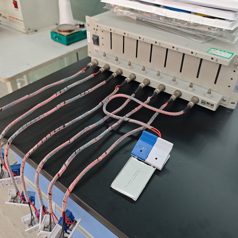
Long-Term Stability and Validation Testing
Even perfectly matched components are subject to a slight resistance drift due to washing, flexing or age. The testing of these is done by validation testing to ensure that they are stable.
To understand durability factors, check this analysis of wash-induced electrical stability changes.
Conclusion — Resistance and Voltage Must Be Engineered Together
In wearable heating with a battery, resistance and voltage are independent variables that pose inefficiency, reduced life span and safety concerns. Electrical thinking System-level electrical thinking (beginning with target power, choosing a suitable voltage platform, and designing resistance based on that choice) provides predictable, reliable results. This is a rigorous practice between strong design and those likely to fail in the field.