
Developing a custom app-controlled heating system is a structured engineering process that requires coordinated design of software, electronics, power management, and thermal output—not simply adding an app to an existing product. Successful system development begins with architecture planning, not with mobile app interface design. Many brands mistakenly assume the process starts with designing a sleek app UI, but in reality, it must begin with defining the overall system architecture and ensuring power coordination across hardware components. Without this foundation, issues like inconsistent heating, rapid battery drain, or safety failures often emerge during later stages, leading to costly redesigns.
This guide walks through the essential steps based on real-world experience in wearable heating electronics, focusing on the technical decisions that determine performance, reliability, and scalability.
Step 1 — Define Product Architecture and Control Requirements
The foundation of any reliable custom app-controlled heating system lies in clearly defining the product architecture before any circuit or code is written.
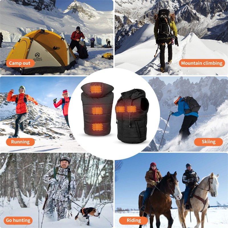
Start by specifying the target product category—whether heated insoles, gloves, jackets, vests, socks, or pants—as this directly influences heating zone layout, power demands, and user interaction needs. For example, gloves require precise, localized control in fingers and palms, while jackets benefit from multi-zone setups across core body areas.
Key early decisions include the number of heating zones (single vs. multi-zone for independent control), desired control precision (fixed temperature steps vs. variable PWM-based fine adjustment), battery voltage (commonly 7.4V for balanced power/weight or 11.1V for higher output), and target runtime/capacity.
Communication protocol is another critical choice, with Bluetooth Low Energy (BLE 5.0 or later) being standard for low-power, reliable app pairing.
| Requirement Category | Key Decision |
| Heating Zones | Single / Multi-zone |
| Control Precision | Fixed / Variable |
| Battery Voltage | 7.4V / 11.1V / Custom |
| Communication | Bluetooth version |
These choices shape every downstream element. For brands exploring options, partnering early with experienced teams in custom app-controlled heating solution development helps align architecture with manufacturing realities and market needs.
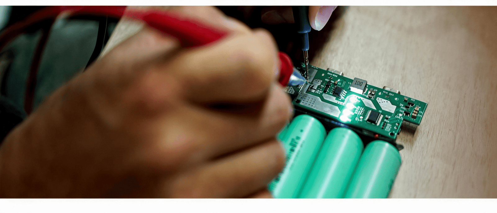
Step 2 — Controller and PCB Design
Controller selection and PCB layout form the central nervous system of the heating setup, handling signal processing, power delivery, and safety.
Choose a microcontroller unit (MCU) with sufficient processing speed, GPIO pins, and BLE stack support—options like Nordic nRF52 series or STM32 with integrated wireless often prove reliable for wearable constraints.
Signal routing must minimize noise and interference, especially in flexible garments where flexing occurs. Current regulation is vital: use MOSFETs or dedicated drivers capable of handling peak loads without excessive heat buildup in the controller itself.
Integrate layered safety protections from the start, including over-temperature cutoffs, short-circuit detection, and low-voltage lockout.
| Controller Aspect | Why It Matters |
| MCU capability | Processing speed |
| Current smoothing | Stable heating |
| Thermal protection | Safety compliance |
| Firmware flexibility | Future scalability |
Poor controller design leads to flickering heat output or premature failures under variable loads.
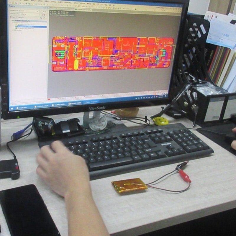
Step 3 — Firmware and App Integration
Firmware serves as the bridge between user intent (via the app) and physical heating behavior, so its logic must be robust and testable.
- Define the communication protocol early—typically GATT services over BLE for commands (set temperature, query status) and notifications (battery level, current temp).
- Implement temperature mapping logic: convert user-selected levels (e.g., 1–10) into precise PWM duty cycles based on real-time sensor feedback from NTC thermistors placed near heating elements.
- Establish app-controller handshake: secure pairing, reconnection logic for dropped connections, and over-the-air (OTA) update capability for future fixes.
- Run iterative debugging cycles: simulate edge cases like low battery, rapid temp changes, or interference, then refine firmware before hardware integration.
This sequence prevents common pitfalls where app features look polished but fail under real usage due to mismatched firmware responses.
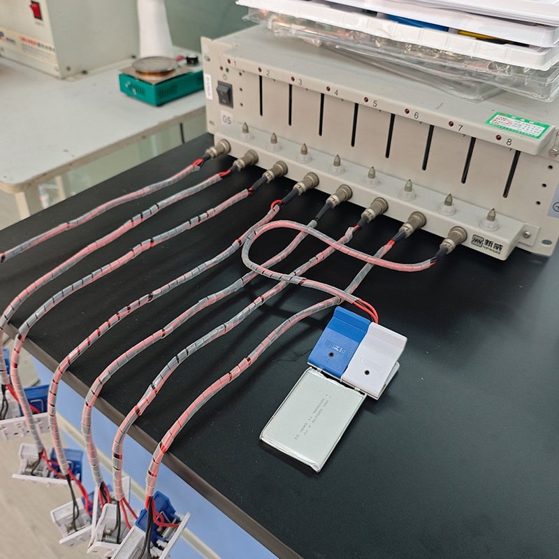
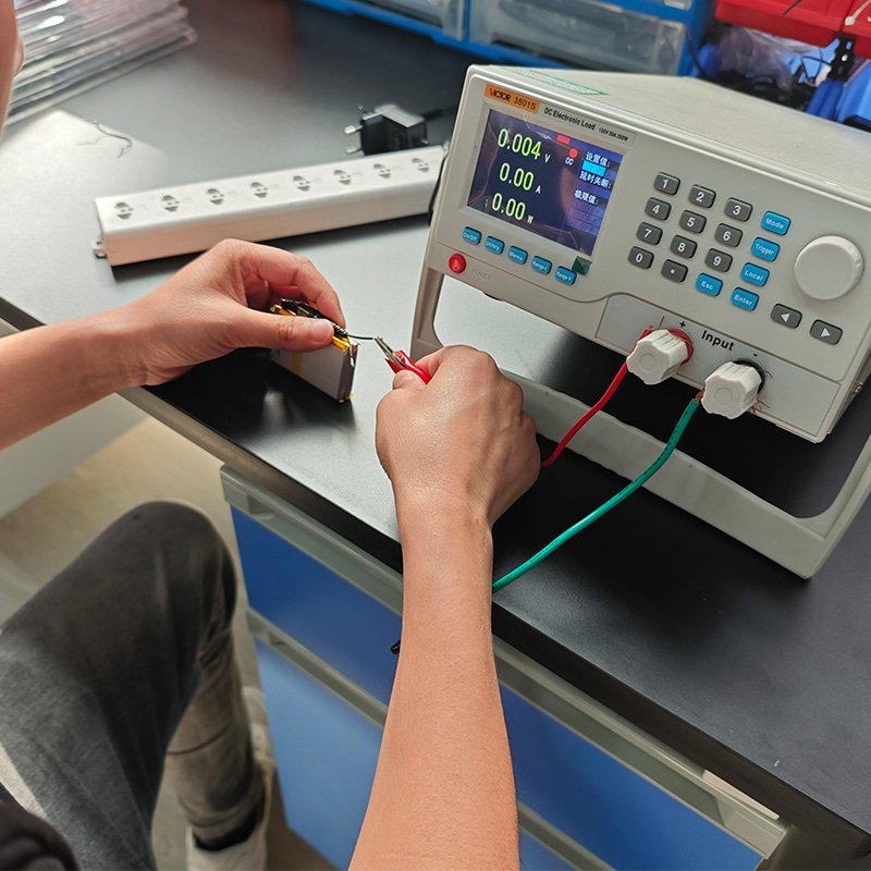
Step 4 — Battery Management and Power Coordination
Power stability directly affects user satisfaction—fluctuating voltage causes uneven heating or sudden shutdowns.
Select a Battery Management System (BMS) that supports the chosen cell configuration (e.g., 2S for 7.4V), with cell balancing, overcharge/over-discharge protection, and temperature monitoring.
Conduct load testing under maximum draw scenarios to verify voltage droop remains within acceptable limits for consistent heating.
Incorporate overcurrent safeguards and runtime optimization algorithms that adjust power based on remaining capacity.
| Power Factor | Development Consideration |
| Voltage stability | Consistent heating |
| Overcurrent control | Component safety |
| Runtime optimization | User satisfaction |
Mismatched battery and controller specs often cause the most field failures.
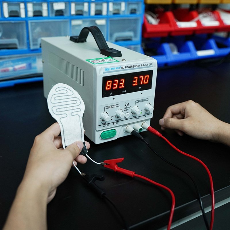
Step 5 — Heating Element Mapping and Thermal Distribution
Heating elements must deliver uniform warmth without hotspots, especially in flexible, body-conforming garments.
Plan element placement based on thermal imaging of the target anatomy—e.g., larger pads over core torso in jackets, segmented wires in glove fingers.
Use carbon fiber or etched foil elements for even resistance distribution, coordinating with insulation layers to direct heat inward while minimizing outward loss.
Garment integration requires considering seam placement, washability, and flex durability—elements should withstand repeated bending without resistance drift.
Structural integration here prevents post-production complaints about cold spots.
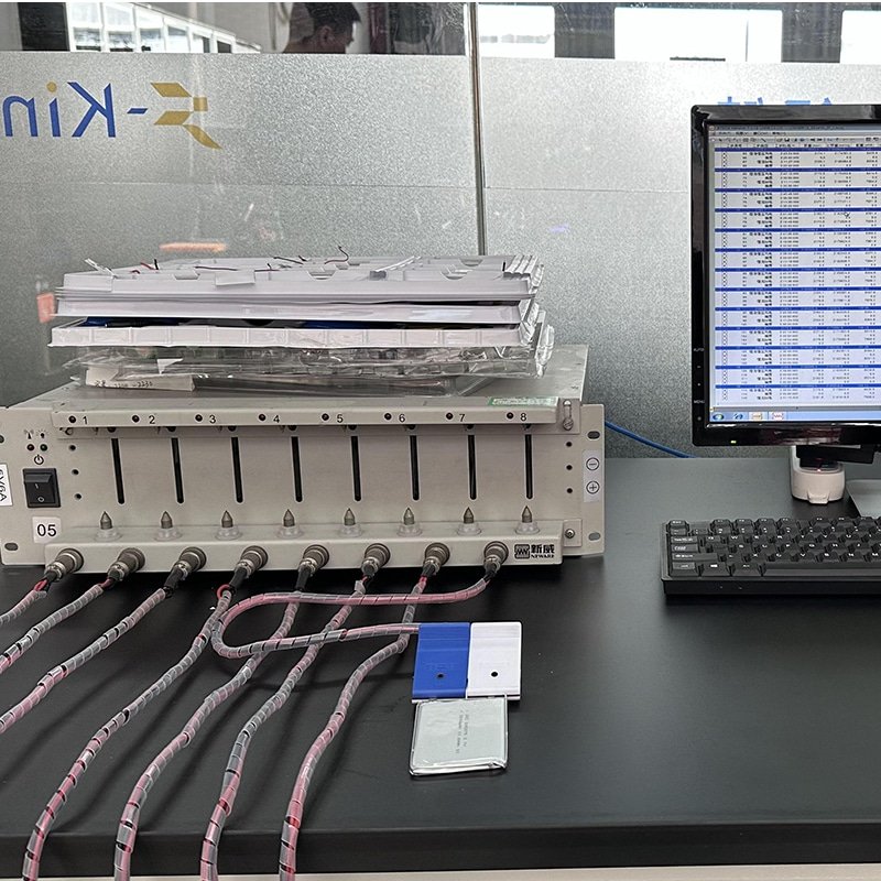
Step 6 — System Testing and Validation
Validation confirms the integrated system performs safely and reliably under real-world conditions.
Perform over-temperature testing by forcing maximum load in insulated chambers, monitoring for runaway scenarios.
Run endurance cycles (thousands of on/off and flex cycles) to verify long-term stability.
Test signal integrity during motion and interference to ensure BLE remains responsive.
Conduct full aging tests simulating years of use, including battery cycle life and thermal drift.
Engineering validation at this stage catches issues before production scaling.
Development Risks Brands Should Evaluate
- Insufficient firmware testing leading to unreliable temperature control or app disconnects
- Incomplete signal stability validation causing dropped connections in real environments
- Battery mismatch risks resulting in short runtime, overheating, or safety events
- Scaling production challenges from unproven component tolerances or assembly variations
Evaluating these upfront, with prototypes and iterative testing, reduces launch risks significantly.
Conclusion — Custom Development Requires Architecture Discipline
Custom app-controlled heating system development succeeds when architecture, power management, firmware, and thermal mapping are engineered as one integrated framework rather than as isolated features. By following a disciplined, step-by-step process that prioritizes coordination across all layers, brands can achieve reliable performance, safety compliance, and scalability—delivering smart heated apparel that truly meets user expectations in demanding cold-weather scenarios.