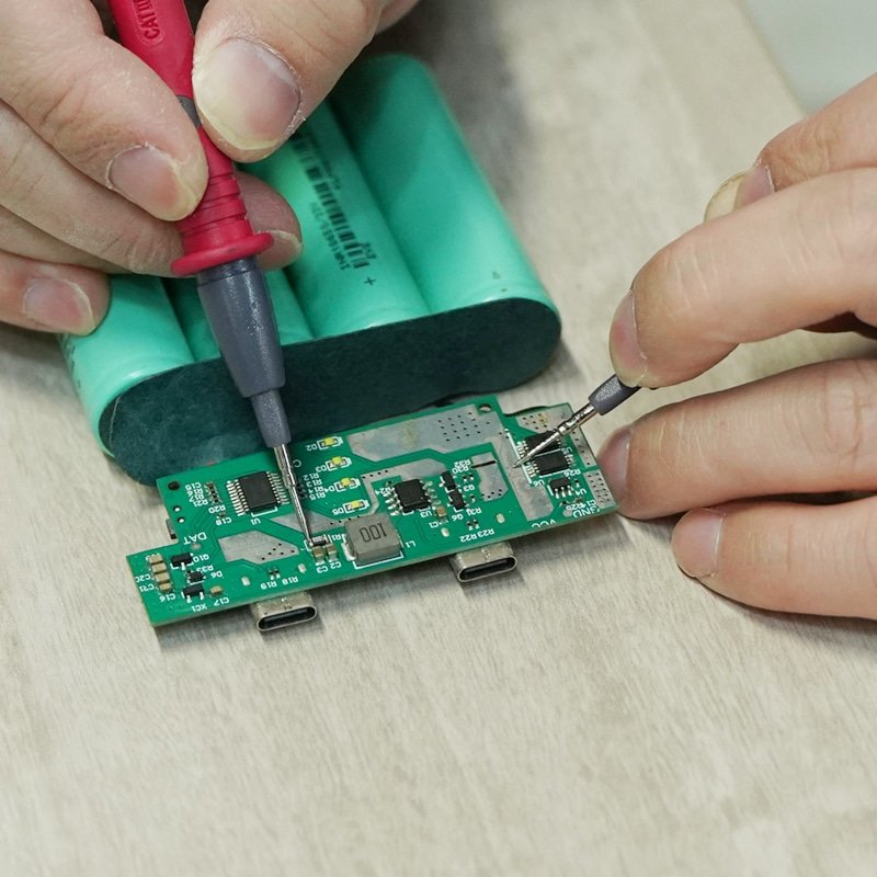

PCBA layout is by itself the largest area of influence in the heating performance of battery-powered heated jackets, vests, and gloves, as well as other wearables. Most OEMs are working on the amount of mAh the power supply will carry; however, the performance of real world is much more measured by the efficiency of power to flow through the board, the cooling of the heat, and the distribution of current to heating components. Unplanned off-the-shelf PCB is not only energy-wasting but leads to even lighting, power distribution, and decreased run-time, all of which cannot be completely addressed by a large battery pack.
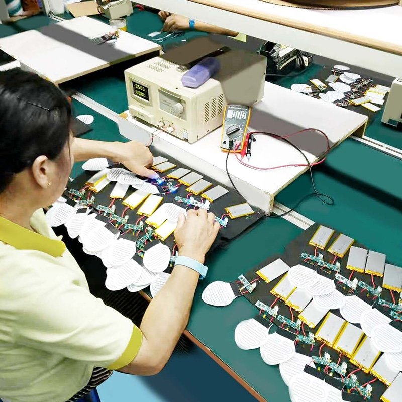
Why PCBA Layout Determines Heating Performance
Heated wearables have strict requirements: small battery capacities, high power consumption (310A+), and the cause of equal warmth near the body.
The printed circuit board assembly (PCBA) is considered the central nervous system and it distributes power, regulates heating status and governs thermal characteristics. Optimal layout results in efficient transfer of energy to heating wires with minimal energy wastes, equal distribution of heat and balanced discharge in the battery.
At layout: When layout is not taken into account, the system undergoes:
- Significant voltage drops
- Localized thermal hotspots
- Unstable peak currents
- The premature deactivation of battery.
Such problems can cut the effective heating time to 20-40-percent of that of a well-designed board with the same battery.
Power Routing Losses and Energy Waste
The Hidden Cost of Inefficient Power Paths
Heating elements are very current intensive and even small trace resistances are converted to large energy loss.
Even a single milliohm of power that runs through the path does not transform precious battery energy into useful, life-sustaining warmth but rather, undesired heat on the PCB.
Key Factors That Create Power Loss
- Slim or slender copper tracks or tracking in a circuit -> high resistance of the circuit and the circuit gives large IR volts drop.
- Thickness of copper conductor (e.g. 0.5 oz, rather than 1–2 oz in the case of high-current paths)
- Annually excessive vias that were not needed to be stitched.
- Prolonged pathways between battery connection and heating outlet.
Voltage drop of 0.3-0.6 V in load: mediocre designs have a voltage drop under load of 0.3-0.6 V, so the system must like to take more current to sustain the heat output – exponentially increasing battery discharge.
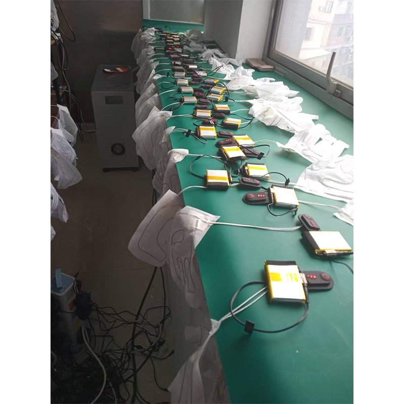
Best Practices for Low-Loss Power Delivery
Designers can reduce losses by employing broader traces, special power planes, small routing paths and large copper pours.
Our guide to low-loss PCBA power routing of heated wearables covers low-loss PCBA power routing for heated wearables.
Thermal-Aware Layout and Heating Consistency
Why Heat Management on the PCB Matters
Power semiconductors (particularly MOSFETs utilized to oversee PWM heating) release an average of a lot of heat when running. An incorrect positioning makes the board to become a cluster of hotspots rather than a homogenized system.
Common Thermal Design Mistakes
- MOSFETs are overcrowded together: extremely high concentration of heat.
- Components that are on high-heat and are connected to the battery or to control ICs via connectors or other interconnection surfaces = Thermal coupling.
- Absence of thermal vias or copper dissipation space = trapped heat.
Such issues result in uneven heat distribution, low component reliability, and likely safety issues.
How to Achieve Thermal Balance
Placement of strategically positioned components, thermal vias array, extensive copper heat-spreading planes, and adequate design of the ground plane maintain temperature to acceptable levels and provide warmness throughout the garment.
Since it is too time-consuming and costly to experiment with well-developed strategies,see our detailed article on thermal-aware PCBA layout for electric heating systems.
Battery Stress Caused by Poor PCB Design
How Layout Affects Battery Health
The battery life does not only cover capacity, but the softness with which the cells are discharged.
Failure to design PCBA layout appropriately will subject Li-ion batteries to severe conditions typical of overuse:
- Acute spikes of peak currents during heat initiation.
- Ripple and voltage instability.
- BMS protection circuits frequently blown.
- Lepisodischarging in multi-cell packs.
Long-Term Consequences
Such stress modes raise the level of internal resistance, hasten degradation, and shorten cycle life – even up to 30 to 50 percent of the useful life with compared to batteries in optimally designed different combinations.
Creating Battery-Friendly Operation
Constant current delivery, reduced peak loads and clean voltage regulation enables the battery to be driven into the operating region that correctly fits the discharge curve of the battery – conservation of capacity and increasing cycle life.
Find out in our guide about the already tested strategies of battery-friendly battery-friendly PCBA layout strategies for heated clothing.
Layout vs Real-World Heating Runtime
Theoretical battery capacity can hardly equal the actual heating time of the heating matters – and PCB aspect lay out has more explanations in most cases.
Poorly designed systems will end up wasting 15 percent to 30 percent of the energy before energy reaches the heating component. These losses increase with the warming up of the board (as trace resistance increases) and with the voltage across the battery, under load.
Optimized layouts are very efficient in the discharge cycle providing longer, more continuous heating sessions.
In practice, it has always been demonstrated that a layout efficiency focus can increase usable life by a factor of 20-40, as compared to the lifetime of an average commercial design with the same battery.
Learn how top manufacturers achieve this in our article on optimizing PCBA layout to extend heated apparel battery life.
OEM Checklist: The Most Critical Layout Decisions
To design or test PCBA to wearables that have to be heated, ensure that the following are met with the necessary importance:
- Sufficient trace width and copper mass of all high-current tracks.
- Positioning of MOSFETs and other components of power.
- Good thermal vias, copper pours and heat-spreading planes.
- Reduced voltage drop and ripple current.
- Constant supply of power to eliminate BMS nuisance trips.
- Isolation of thermal dissimilar components and heat sources.
- Through thermal imaging and full load operating experience.
Achieving such features will result in higher heating fidelity, longer battery life, and a higher level of customer satisfaction of your heated wearables achieving marked competitive advantage.
Ultimately, reading battery capacity is just a headline, but intelligent PCBA layout is the one that is capable of providing excellent heating performance and battery life in real-life scenarios.
Frequently Asked Questions
What copper weight should a high-current heating path use?
1 to 2 oz rather than the 0.5 oz that suits signal routing. The heating path carries amps continuously, so a thin copper layer turns a measurable share of the pack’s energy into heat inside the board instead of inside the garment. Thick copper is also what keeps the temperature rise of the board itself predictable.
How much does via count matter on the power path?
More than most layouts assume. Every via adds resistance and thermal impedance in series with the load, and the effect multiplies when the current is several amps. High-current routes should use the minimum number of vias, stitched in parallel where a layer change is unavoidable.
Can layout alone change how long a pack lasts?
Yes. A poor power path wastes energy before it reaches the element, and the resulting voltage drop makes the controller work longer to deliver the same warmth. Boards that get this wrong have been measured at a fraction of the heating time of a well-laid-out board on an identical pack — the battery is blamed for a layout problem.
What should a layout review check first?
The power loop: its length, its cross-section and where it shares copper with sensitive signals. Then the ground return, then the distance between heat-generating devices and the temperature sensor. Getting the loop right first usually removes the thermal problems that would otherwise be solved by adding components.